Home Network Segmentation with Openwrt
Outline
The aim of this post is to show/document how to configure a simple network segmentation using OpenWRT and untagged VLANs. I’m using an OpenWRT router as well as two simple unmanaged switches. One switch is used for an “IOT” VLAN containing a FireTV Stick and a Hue Bridge. The other switch is used for a “SERVICES” VLAN containing my local DNS server (Pi-hole) and my NAS. One of the remaining four ports of the router will be bridged with the WiFi and the bridge will be assigned to a “WiFi” VLAN containing my Chromcast Ultra (attached to the LAN port), my Stadia Gamepad and my Smartphone. The the last port of the routed will be assigned to a “lan” VLAN for my notebook/docking station. Figure 1 displays this setup with different colors for each VLAN.
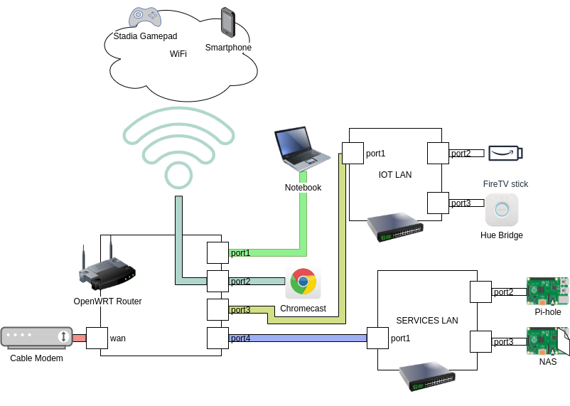
Figure 1: Network architecture with different colors for each VLAN.
Configure VLANs
The first step is to configure the VLANs. Go to Network->Switch to configure your desired VLANs. First off make sure that “Enable VLAN functionality” is checked. In the VLAN matrix, the first column (CPU (eth0)) should be left to tagged (default). All other elements should be set to “off” except for the VLANs you want your respective ports to be in. In my example, VLAN ID 1 is on LAN port 1, this is the “lan” VLAN for my notebook. VLAN 2 is the VLAN for the WAN port. VLAN 13 is my “IOT” VLAN and assigned to LAN port 3. VLAN 23 is the VLAN I want to use for WiFi as well as for LAN port 2. A device plugged in to LAN port 2 will be in the same VLAN as the devices that are connected via WiFi. If you want a VLAN just for WiFi you can set everything (except CPU (eth0)) to “off”. VLAN 33 is the “SERVICES” VLAN for my internal services (DNS, NAS, …). I am using untagged VLANs because I only have unmanaged switches attached to the LAN ports which don’t support tagged VLANs. This means the distinction between the VLANs happens on the router only, the devices attached to the ports will know nothing of the VLANs. Figure 2 shows my configuration.
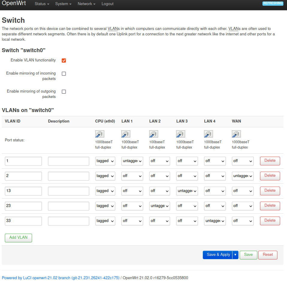
Figure 2: VLAN configuration in Network->Switch menu.
Configure Firewall Zones
After you have created your VLANs, you need to create firewall zones. Each VLAN needs to have its own firewall zone. In Network->Firewall add a zone for each VLAN. In my example, the VLAN “lan” is my trusted internal VLAN. It has a configured forwarding to the “WAN” zone which means all outgoing (to the Internet) communication is forwarded through the “wan” zone. It’s Input chain is set to “accept” so it can talk to OpenWRT on any port. “IOT_LAN”, “SERVICES” and “WIFI” are untrusted and are by default rejected, which means connections to the Internet are not automatically forwarded and systems in these VLANs will by default not be able to send packets to the Internet. Their input chain is set to rejected which means they are also by default not allowed to send packets to the OpenWRT device. Figure 3 shows my firewall zone configuration.
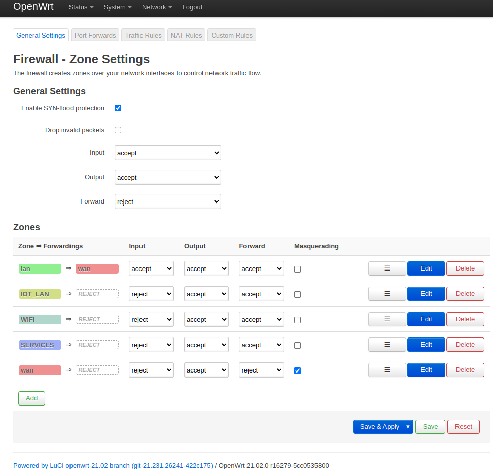
Figure 3: My firewall zone configuration.
Explanation of Zone=>Forwardings, Input, Output and Forward
- Zone=>Forwardings - Traffic forwarding from zone a to zone b
- Input - Traffic to the router from the current zone (used for dns/dhcp, openwrt webinterface, ssh, …)
- Output - Traffic to the current zone from the router
- Forward - Traffic between networks in the current zone (only relevant if you have multiple networks within one zone, not relevant in our use case)
Configure Interfaces
Next configure your network interfaces. I have one interface per switch port and in case of LAN port 2 I have added a bridge device (see [Configure WIFI bridge](##Configure WIFI bridge)). I will not be going into interface configuration details, just configure them according to your needs and assign the firewall zones. Figure 4 shows how to assign the firewall zone to the network interface. Figure 5 shows my network interfaces configuration.
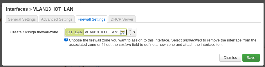
Figure 4: Assign firewall zone to network interface.
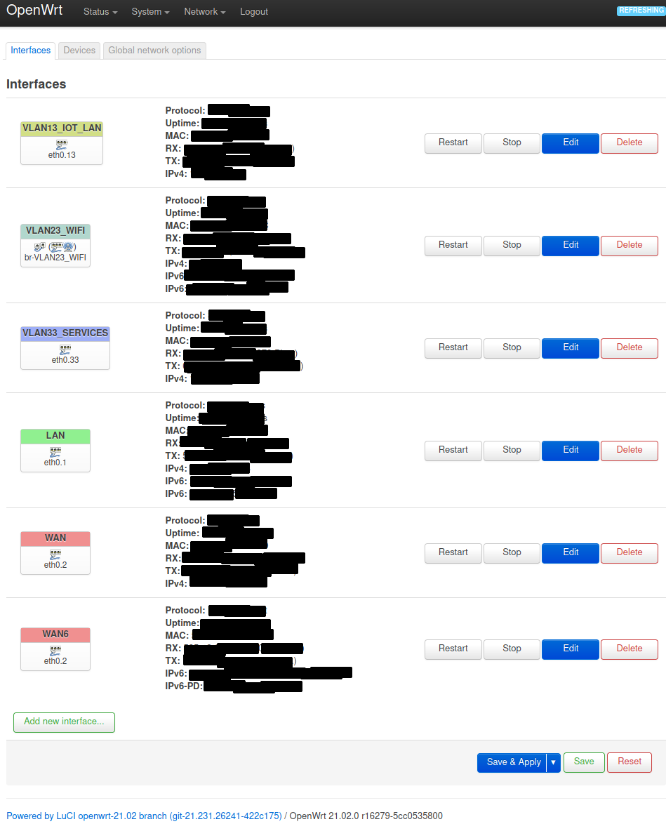
Figure 5: My network interfaces configuration.
Configure WIFI bridge device
If you want to connect LAN port 2 to WiFi you need to create a bridge device. You can do this if you go to Network->Interfaces and select the tab “devices”. Click on “Add device configuration…” and create a bridge as shown in figure 6.
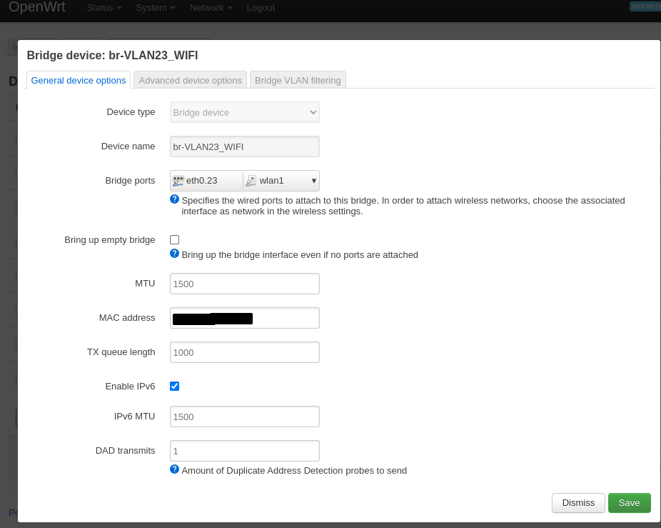
Figure 6: Create a WiFi bridge device.
Apply traffic rules
In the previous steps we have created the basic firewall zones. In this state none of the newly configured VLANs are be able to talk to each other or the router and only the VLAN “lan” is allowed to talk to “WAN” (and therefore the Internet) and the router.
To configure specific traffic forwarding rules between the VLANs, go to the “Traffic Rules” tab in Network->Firewall. In this tab you can configure exceptions for all the traffic you want to explicitly forward.
Traffic to the router
First you need to allow essential traffic from your untrusted VLANs to the router. Which ports you need is depending on your setup, for my setup only DNS and DHCP is required. Figure 7 shows my configuration.
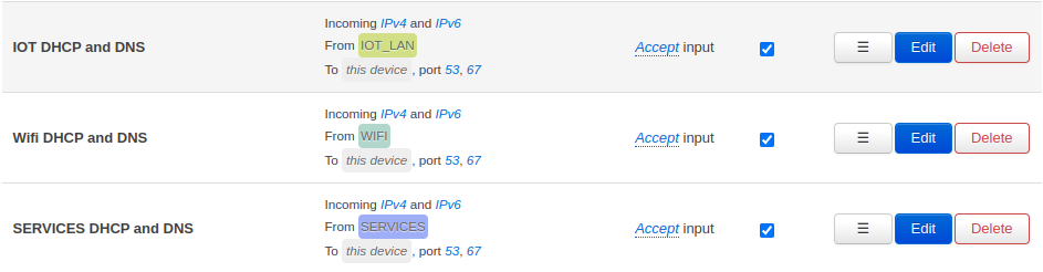
Figure 7: Forward DNS and DHCP traffic from untrusted zones to the router.
Traffic to WAN/the Internet
Next, to allow basic communication to the internet, your need to configure forwardings to the “WAN” VLAN. In my use case I only require HTTP and HTTPs. Figure 8 shows my configuration.
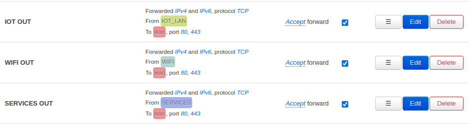
Figure 8: Forward HTTP and HTTPs traffic from untrusted zones to WAN/the Internet.
The Pi-hole needs to be able to access DNS servers so you need to create a custom traffic forwarding for port 53 to WAN. Figure 9 shows this configuration.

Figure 9: Forward DNS traffic from the Pi-hole to WAN on port 53.
Custom ports for WiFi end devices
My smartphone tunnels all traffic through a SOCKS5 proxy using Netguard therefore I need a custom forwarding for that (which is also why I don’t need general forwardings for SMTP and IMAP from WiFi to WAN). My Laptop connects to the Internet using a VPN tunnel so I need a custom forwarding for VPN for when my Laptop is connected to the WiFi. Figure 10 shows this configuration.
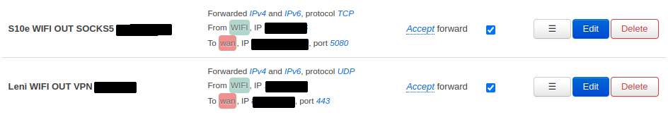
Figure 10: Forward SOCKS5 traffic from the smartphone to a SOCKS5 server and foward VPN traffic from the notebook (WiFi) to a VPN server.
Individual forwardings between VLANs
Finally you need to configure your other individual forwardings between the VLANs according to your use cases. For the pi-hole to work properly, every zone needs a forwarding to the pi-hole on port 53 (Figure 11). To manage the Pi-hole and the NAS via SSH you need to forward traffic for port 22/tcp (Figure 12). Another important configuration is the forwarding of traffic from my smartphone to the Hue Bridge so I can control the lights (Figure 13).
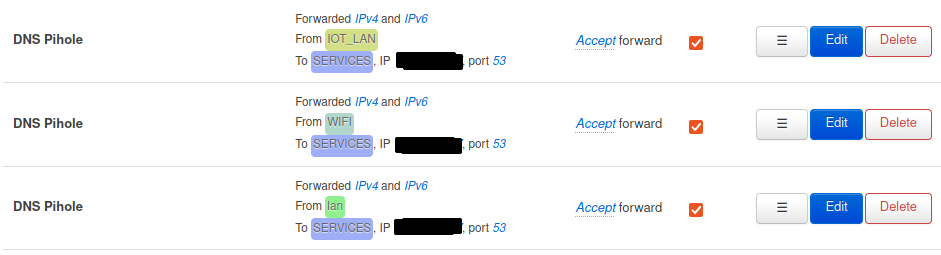
Figure 11: Forward DNS traffic from internal zones to the Pi-hole.
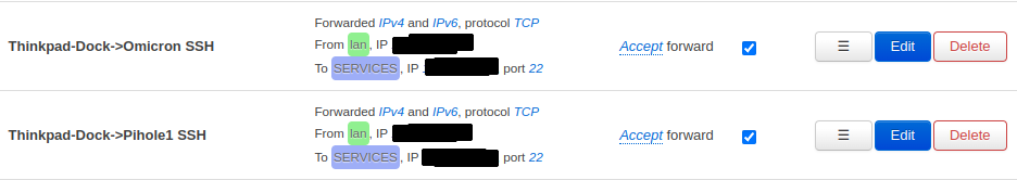
Figure 12: Forward SSH traffic from the laptop to the Pi-hole and NAS.

Figure 13: Forward traffic from smartphone to Hue Bridge on port 80/tcp.
That’s it.